Air Bump Stop · Rev 6 · Automotive-Grade TPU · In Validation
POLYSTOP
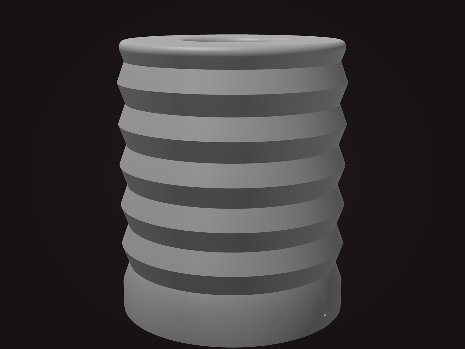
A corrugated annular bellows printed over a central core, closed at the base, forming a sealed air chamber. Compressing the stop displaces the volume inside it, and that air has one way out: vents in the base. Vent area sets how fast the chamber can empty, and that is what makes the response rate dependent. A fast hit outruns the vents and the chamber carries the load. A slow squat gives the air time to leave and the stop stays compliant.
A rubber or foam stop cannot do this. It makes force by how far it is squashed, full stop, so a 2 mph load and a 20 mph load look the same to it. Three revisions went into proving that point the hard way: no choice of compound gets you rate dependence out of a solid part.
- Sealed air chamber, vented at the base
- Vent area sets the rate response
- Velocity sensitive: stiff on rapid compression, compliant on slow
- Approximately 2.5 in outside diameter, approximately 3 in tall
- Universal bolt-through mounting interface
- Automotive-grade TPU, 3D printed in-house
Pricing coming soon
Validation in progress. Preorders open when road testing is complete. QUESTIONS → [email protected]
Seven revisions, failures included.
The architecture changed partway through. Revisions 1 through 3 tried to get a staged response out of solid elastomer geometry, tuned by compound and profile. Rev 4 onward is an air chamber. Both eras are on the record here, because the second one only exists because of how completely the first one stopped working.
Rev 1Early revisions
A computationally tuned buckling geometry in a solid elastomer, intended to fold predictably under load.
Failed at the mounting surface before it could be evaluated at all.
Rev 2
Same approach, with a universal bolt-through mounting interface added.
Manufacturing quality resolved. That mounting interface has carried forward unchanged ever since.
Rev 3The turning point
A softer compound in a simulation-tuned buckling geometry, which should have been the easiest possible case for the part to fold. It still refused to buckle.
That ruled out compound selection as the lever, and proved the problem was architectural rather than material. It ended the tuning approach and started the air-chamber approach.
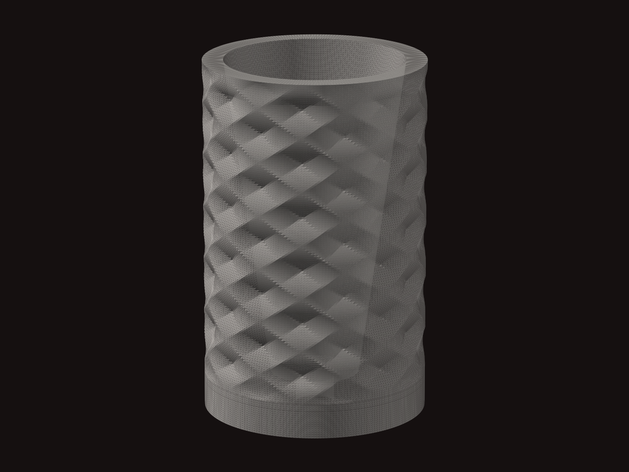
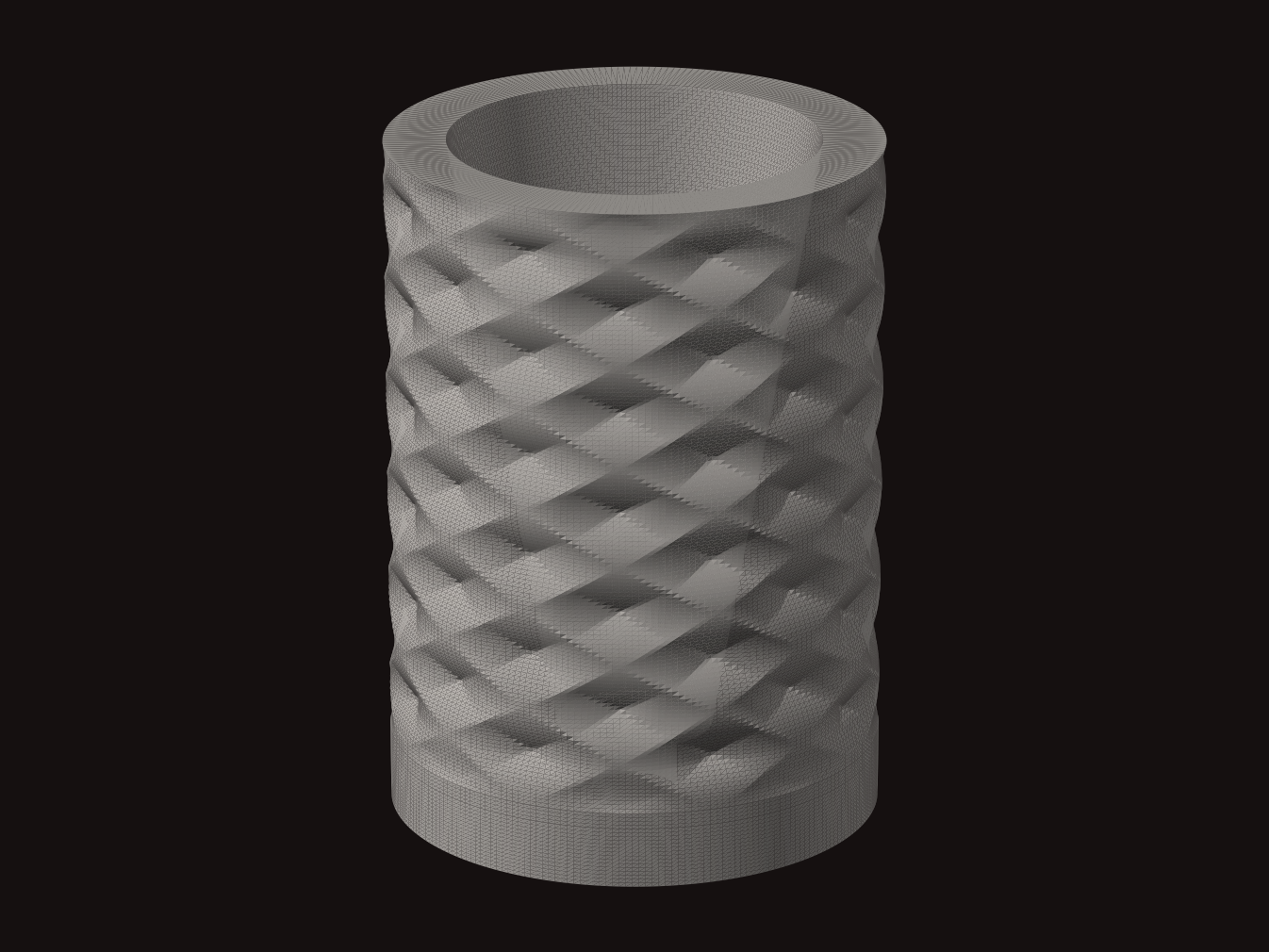
Revisions 1 to 3, the solid-elastomer era, retained as record. This is not what the part looks like now.
Rev 4First air chamber
The first sealed-chamber attempt, with vents in the base. The vents closed themselves during manufacturing, so the chamber came out sealed shut.
Response far too hard. With nowhere to vent, the chamber could not modulate anything.
Rev 5Overcorrection
Thinner walls and substantially more vent area, to make sure the chamber could actually breathe this time.
Too soft. The chamber emptied faster than it could carry load, which put the response back to something a piece of foam could have done.
Rev 6Current
Thicker walls again and sharply reduced vent area, tuned through repeated road testing until the chamber held pressure on a fast hit without locking up on a slow one.
Achieves rate-dependent response: stiff under rapid compression, compliant under slow compression.
Every revision is printed in-house, which is why the loop between a change and a road test is measured in hours.
Rev 7In development
Rev 6 geometry in a higher durometer, for structural margin and to shift more of the load path onto the air chamber on hard impacts.
Rev 3 is the result that mattered. It ruled out an entire class of solution. Softer compound, tuned profile, simulation behind it, and the part still would not buckle, which meant no amount of compound selection was going to produce the behavior we were after. That is what forced the redesign. Everything from rev 4 on exists because rev 3 failed clearly enough to be worth something.
The geometry is the valve.
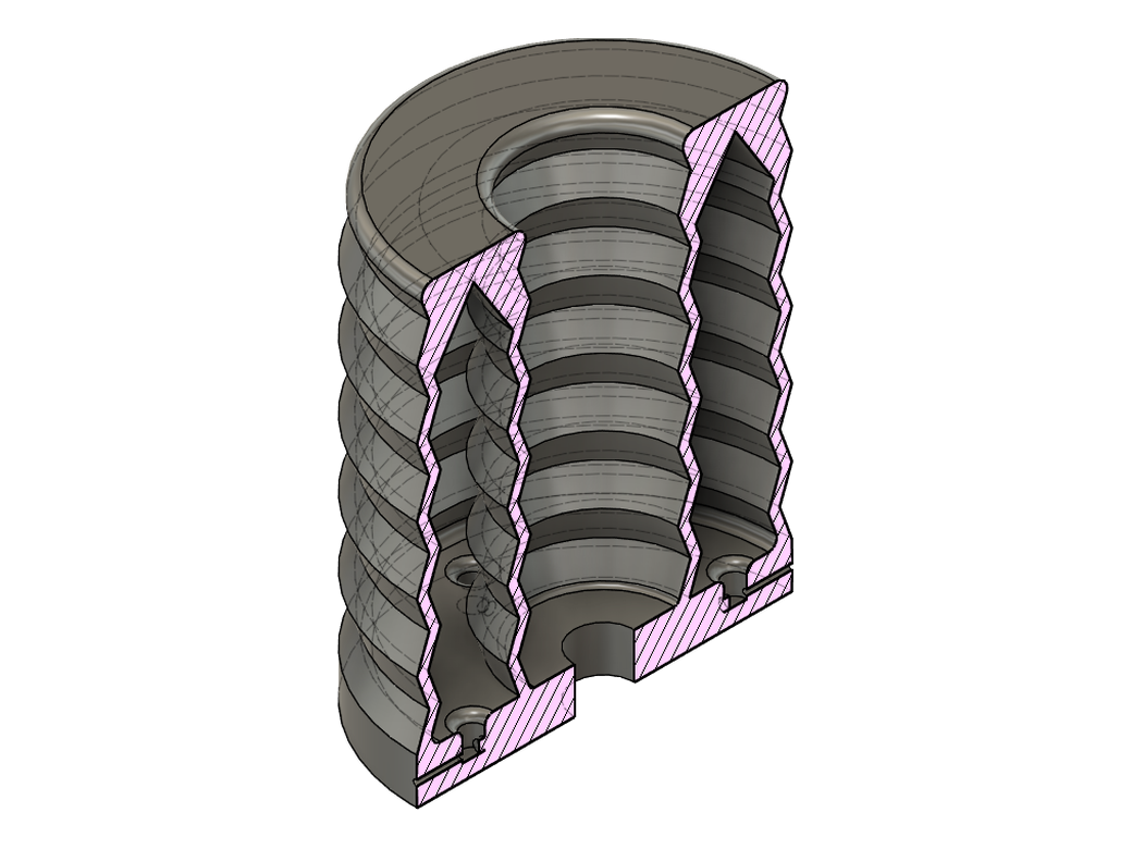
There is no separate valve body, no seal stack, no charge port. A corrugated annular bellows wraps a central core and closes onto a solid base. That assembly is the chamber, the spring, and the metering device at once, and it comes off the printer as one part.
Section view
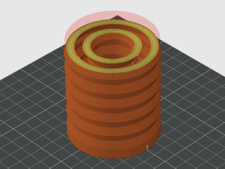
Printed in-house in automotive-grade TPU on industrial-grade FDM equipment. The manufacturing process is the constraint that shaped the whole design: the first air chamber failed because its vents closed themselves during printing, so vent geometry and wall section are chosen to survive the process as much as to hit a target response.
What it is and what it does.
No performance figures are listed, because none have been measured on instrumented equipment yet. What testing has shown so far is in the validation log below.
| Spec | Value |
|---|---|
| Type | Pneumatic air bump stop |
| Response | Velocity sensitive, rate dependent |
| Material | Automotive-grade TPU |
| Manufacturing | 3D printed in-house, Austin TX |
| Mounting | Universal bolt-through interface |
| Outside diameter | ~2.5 in |
| Height | ~3 in |
| Application | Ford F-150, 11th gen (2004 to 2008) and 12th gen (2009 to 2014); F-150 Raptor, 1st gen (2010 to 2014) |
| Status | In validation |
Where testing actually stands.
This is a running log, not a finished result. It gets updated as miles go on the part.
- Bench: rate-dependent compression response confirmed by hand loading on the current design.
- On-road: undergoing hard road testing: jumps, whoops and washboard.
- In progress: additional road miles required before release. External tester on a first-generation Raptor, installation underway.
- Monitored failure modes: fatigue cracking at the fold radii, layer separation under internal pressure, vent deformation over cycles.
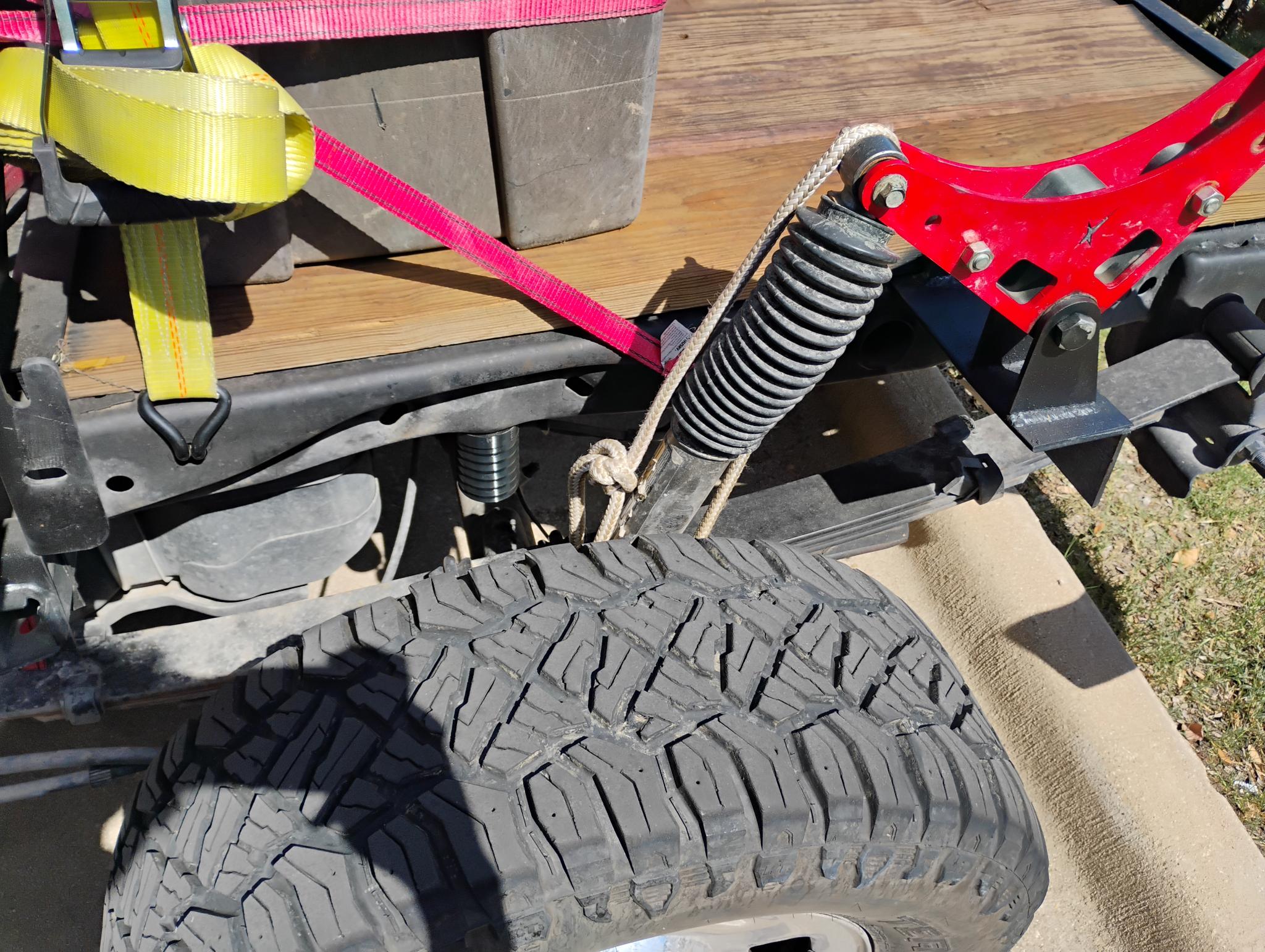
Rev 6 mounted on the test truck. This is where the miles are going on it.
The mileage so far is an early data point. It is not a release threshold and it is not being presented as one. Nothing at this stage speaks to fatigue at the fold radii or to how the vents hold their shape over thousands of cycles, which are the two things most likely to end this design. The part ships when the miles justify it, and not before.
QUESTIONS & FITMENT INTEREST
Not yet available for sale. Road testing is underway on a first-generation Raptor. Email with your platform if you want to hear when preorders open.
Printing and development work